
Hardware requirements
AVGA has yet been successfully tested on theese devices:
- ATMega88
- ATMega16
- ATMega168
- ATMega128 (overclocked to 19.6608MHz)
- ATMega644
How to connect the AVR to a monitor
The system needs one 16bit AVR timer/counter. The horizontal sync signal outputs through OCRxB of the configured timer. Vertical sync output port and pin can be set in config_hw.h. Pixel stream appears at high nibble of a configured port.The pixel stream can be converted using resistor video DAC to RGB compounds with standard 16 color EGA/VGA pallette.
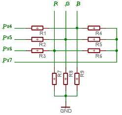
Where R1=R2=R3, R4=R5=R6 and R7=R8=R9;
By adjusting R1:R4 ratio, contrast between lower and upper color page is changed easily. I suggest range from 2:3 to 1:2. Actual resistor values depends on monitor's input levels and impedance. Here are some examples:
-
VGA CRT monitor (75 ohm inputs):
R1=R2=R3=470R
R4=R5=R6=680R
R7=R8=R9=100R
-
Sony PSOne TFT Screen (high impedance inputs):
R1=R2=R3=2k2
R4=R5=R6=3k3
R7=R8=R9=1k
-
Analog PAL TV with SCART connector (75 ohm inputs):
R1=R2=R3=470R
R4=R5=R6=680R
R7=R8=R9=100R

Color palette you get with this DAC
Alternatively, R2R ladder can be used to create 16 color grayscale. Such signal can be for example mixed with VSYNC directly to create B&W composite video.
The SYNC signal voltage should be reduced using resistor divisor to ensure correct input voltage level for your display. Resulting lines: R, G, B and VSYNC (HSYNC) may be connected directly to the monitor (e.g. VGA D-sub, SCART connector...) or to a RGB-to-composite converter unit (e.g. AD725).
The audio signal outputs through OCRxx of the configured timer. A capacitor should be connected between the pin and audio output to remove the DC compound and resistor divisor to reduce the volume.
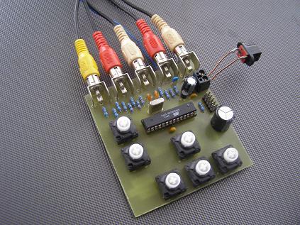
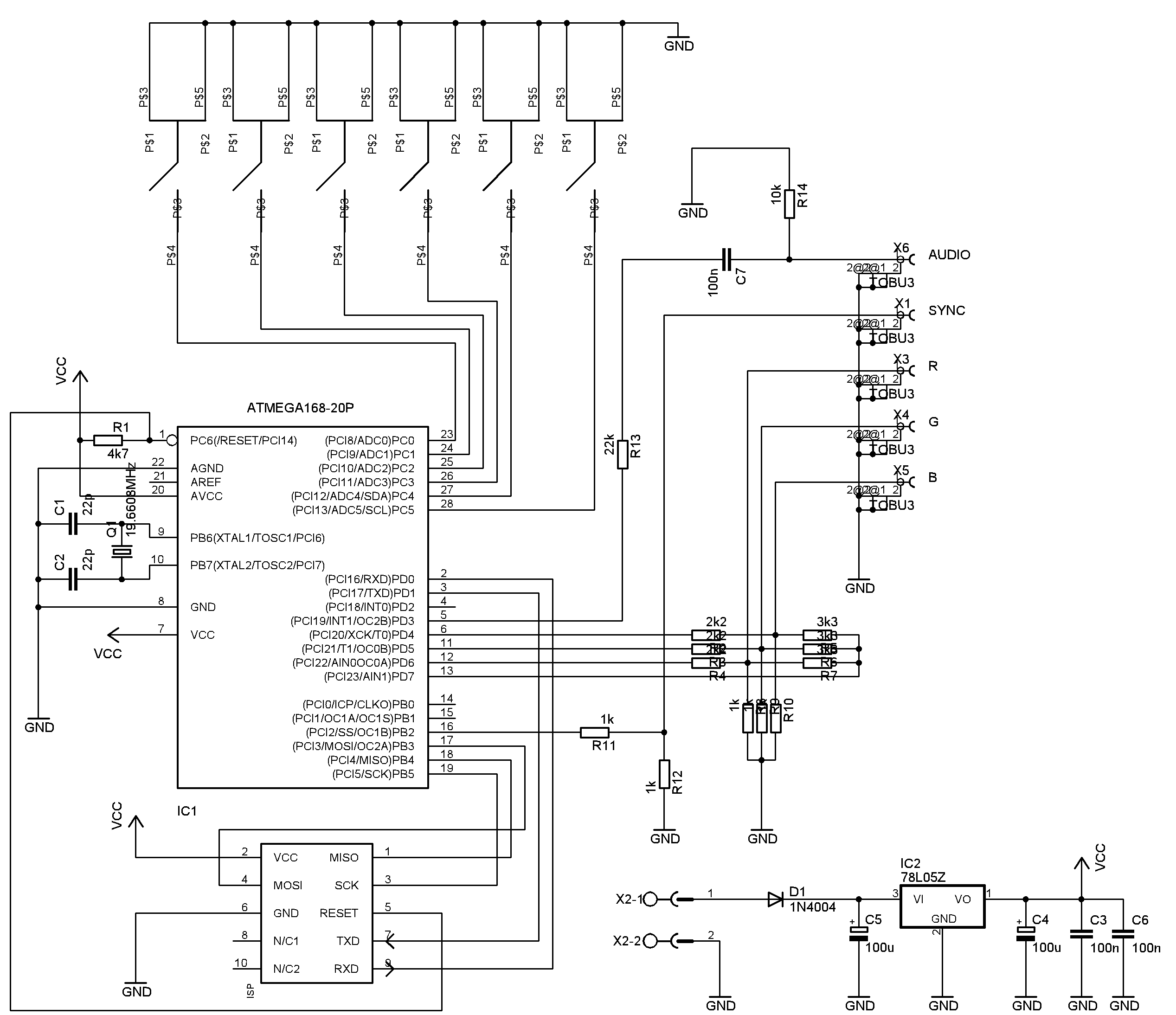
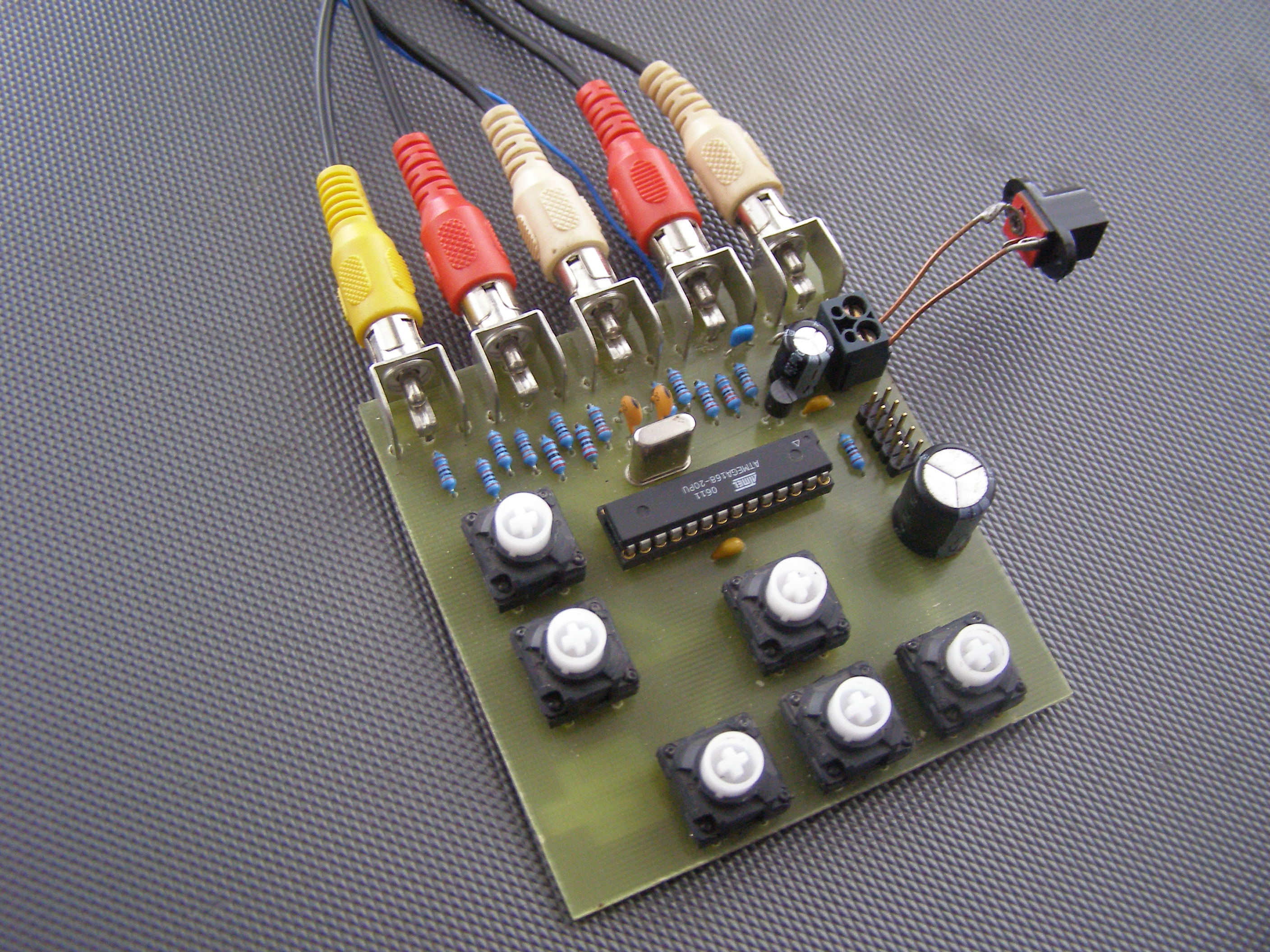
Mega168 development board
Sample project schematics and layouts
Mega168 Development board
MCU:
ATMega168 (DIP) @ 19.6608MHz
Description:
Has RGB resistor DAC, CINCH connectors for audio and each color compound, (VSYNC only),
78L05 voltage stabilizer and six pushbuttons extracted from an old AT keyboard.
Download:
schematic.png
schematic.sch
layout.brd
picture 1
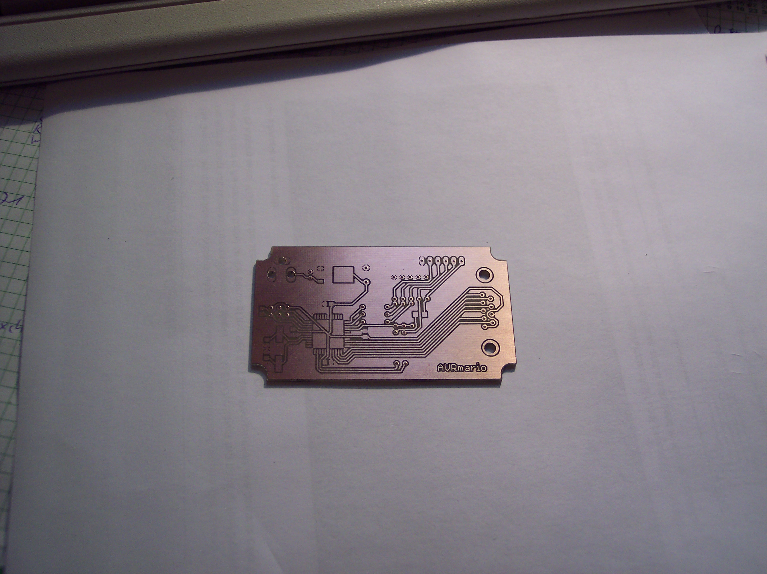
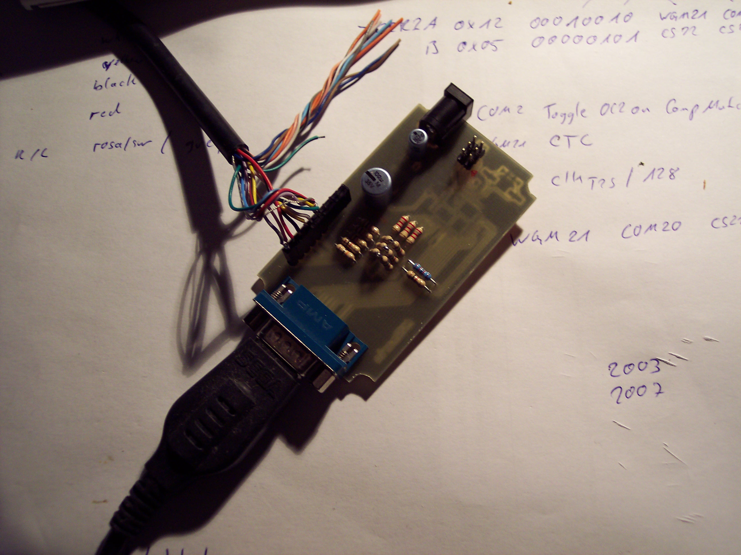
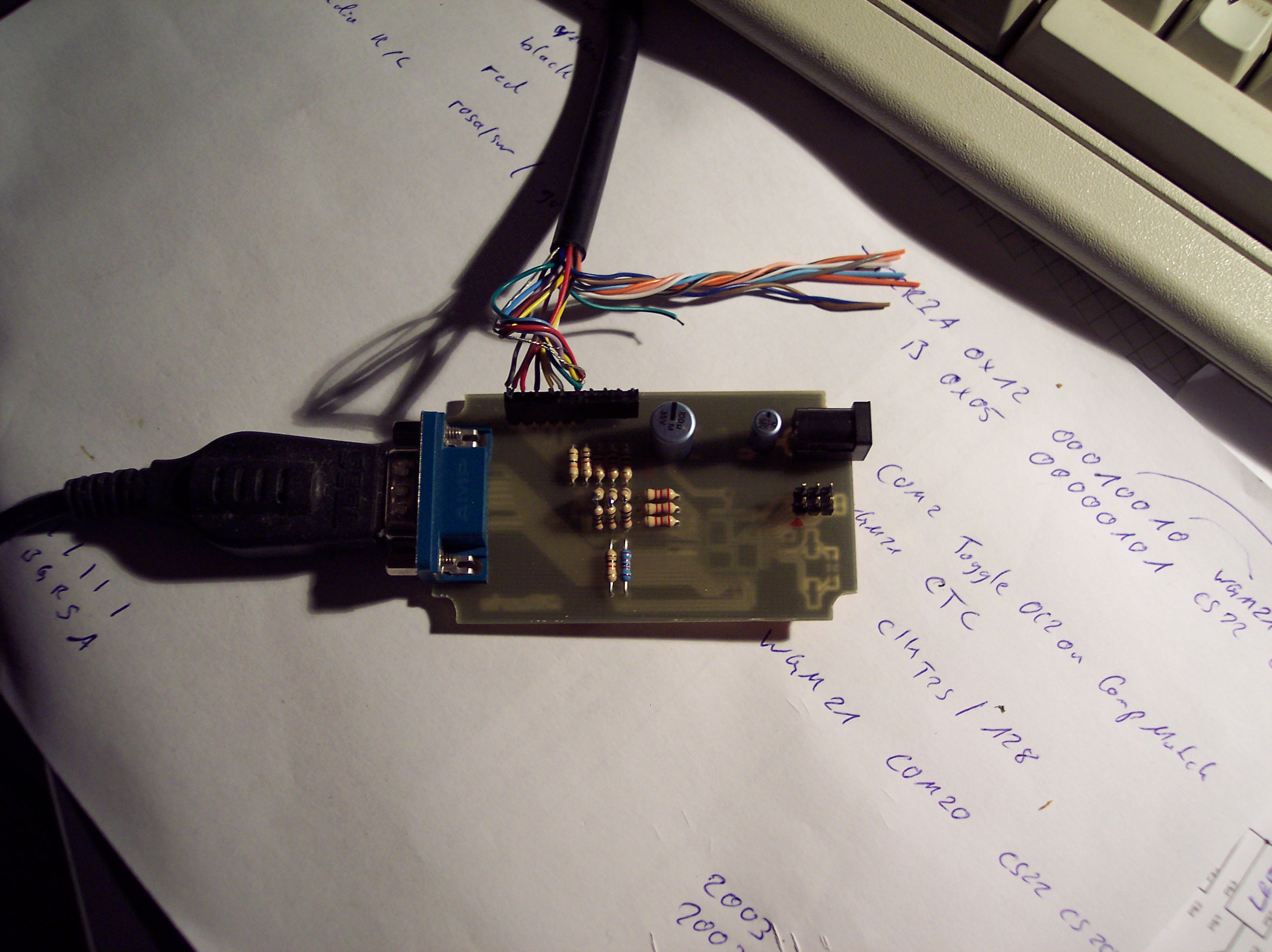
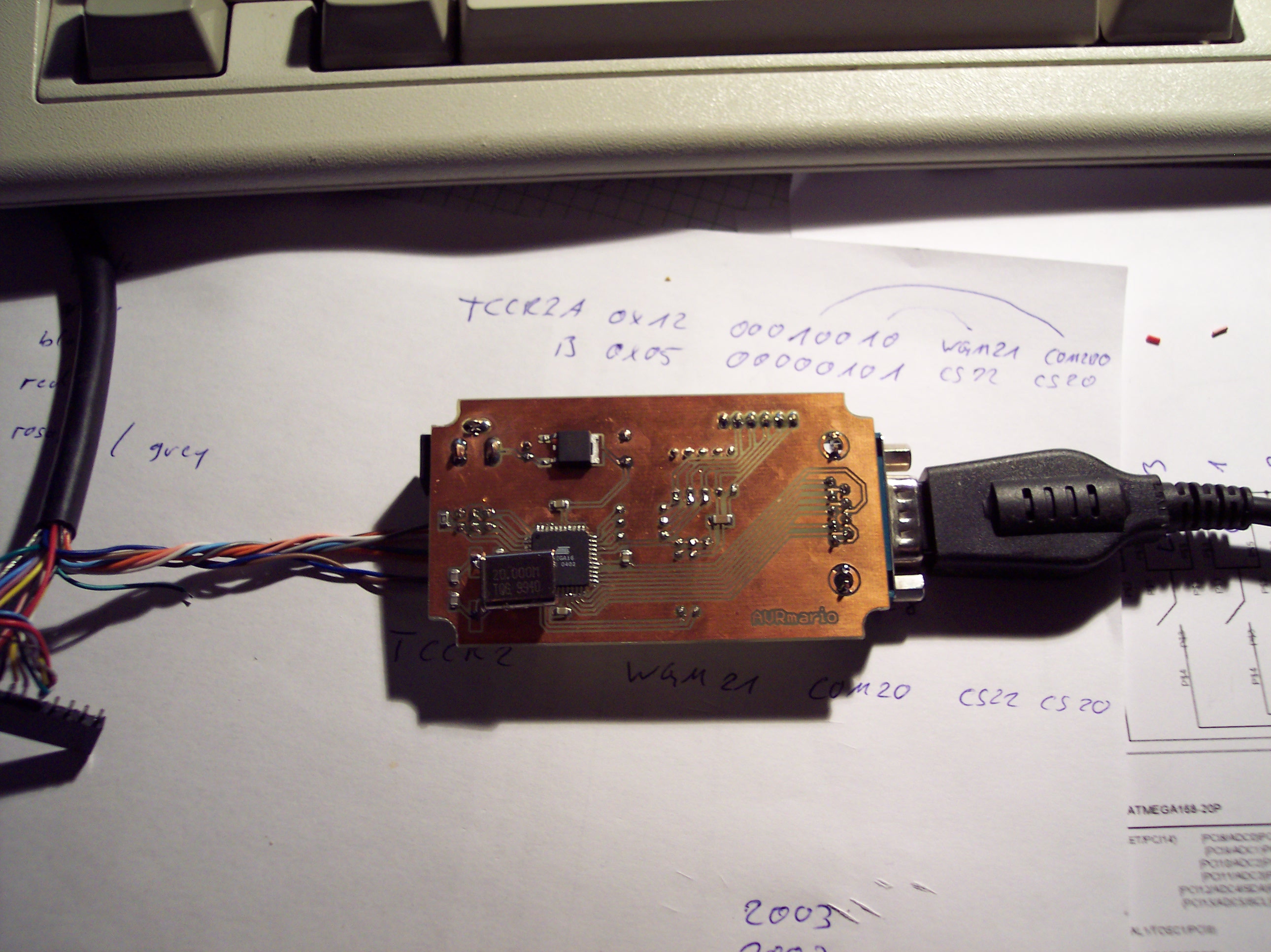
Slime2k's AVRmario
MCU:
ATMega16 (SMD) @ 19.6608MHz
Download:
Supermario.sch
Supermario.brd
Supermario.cmp.pdf
picture 1
picture 2
picture 3
picture 4
Download AVGA config_hw.h for theese samples
| Project name | Hardware configuration file |
| Mega168 development board | config_hw.h |
| Slime2k's AVRMario | config_hw.h |